
How to build them
Auxiliary equatorial disc method
Introduction
This short document does not pretend to be an exhaustive guide for the design of sundials : hundreds of detailed books are available on this topic.
The purpose is mainly to give a simple answer to the question that a dialists is often asked when speaking about sundials : how a sundial can be designed ?
Several methods will so be described in the following paragraph, all of them applicable to a vertical declining dial. More details will be given to the methods that although not really practical can help in understanding the principles that are behind a sundial. Some space will be dedicated to the preliminary measurement of those parameters that are needed for the design. The chapter "Links" gives several references that can be useful for more in depth explanations.
It is worthy to note, at the beginning of this chapter, that everyone, even who never heard about sundials and does not have any knowledge of trigonometry nor of astronomy, can design his own sundial just using the method that is nearest to his experience and to his capabilities.
Experimental method
This is also known as "patience" method as it needs several months before reaching the final result. However everyone could adopt it, the only difficulty being the knowledge of the Equation of Time principle.
Once the desired planar (but not necessarily vertical) wall has been identified, just fix a style in the wall. It could have any orientation, however just for estetical reasons it would be better to have it orthogonal to the wall surface.
Style length should be such that it will cast its shadow on all the surface that is intended to host the dial. It could be preferable to start with the first experiments in summer when the sun is higher in the sky and the shadow is so longer.
Then mark on the wall, for each hour during the day, the point where you see the shadow of the tip of the style.
Be careful that this is the true solar hour and not the mean time that
is showed by our wristwatch. Therefore using a table of the EoT as the
one shown in this document or using a software program that can compute
the value of the EoT for every day in the year (for instance
Dialist’s Companion
or
Orologi Solari) compute the value of the EoT in the current day
and then correct the reading of your watch5.
For instance the 26th of June the EoT is 2m 50s so the sun is
late. Moreover DST is used in summer. Therefore solar noon (12 o'clock)
is at 13:02:50, solar 15 o'clock is at 16:02:50 and so on.
So you should mark a sign on the wall at 8:02:50, at 9:02:50 etc. and
close to each sign you should write the corresponding sun hour (7, 8
etc.).
At the end of the day you will get a picture similar to the one shown in Fig. 19. Do not care if for some hours it will be impossible to mark the sign because the wall is not lighted or because the shadow of the tip of the style is too far away.
After this second step the result should be similar to the one shown in Fig. 20.
Note that some hours that were not marked on the wall in step 1 could now be present in step 2 as the sun is lower in the sky and the shadow is now within the dial surface.
If everything has been accurately accomplished, when you connect with a
straigth line the points corresponding to the same hour
You can also now connect to C all the points that do not have any corresponding point, as all the hour lines have to go through C (in Fig. 21 the points 9, 10 and 16).
We have so obtained all the required hour lines for our sundial.6.
If we wanted to add the date lines too, then we should execute step 1 and step 2 exactely at the solstices (21st June and 21st December) and then connect all the points together.
In order to add the equinox line, as this is a straight line, two points only are needed : just mark the position of the shadow at two different time instants during the equinox day (21st March or 23rd September) and connect them with a straight line (Fig. 22).
The sundial is so finished.
The only additional optional activity that remains is to replace the current style, whose tip shadow shows the time, with a polar one that shows time with the whole shadow and not with its tip only.
The polar style in our dial is simply the style that is fixed in the wall in C and whose tip corresponds to the tip of the current style (see Fig. 23).
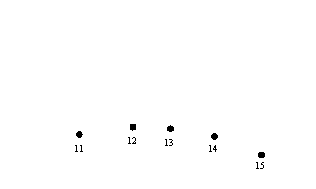
Fig. 19
— Experimental method – step 1
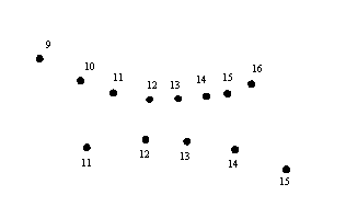
Fig 20 —
Experimental method – step 2
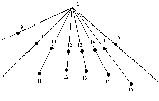
Fig. 21
— Experimental method – step 3
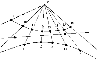
Fig. 22
— Experimental method – step 4
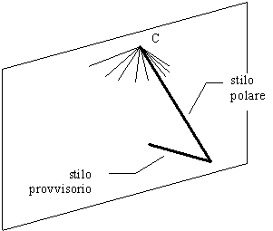
Fig. 23
— Experimental method – step 5
5 Remember the
Daylight Saving Time !
6 If you do not correct
the time with the EoT you would not obtain a single point C as the
crossing point of all the hour lines. Infact in this case two points
marked on the wall would not belong to a hour line but they would just
be two points belonging to the corresponding analemma, and they would
not be necessarily aligned with C. You would have just drawn
random lines instead of hour lines !
Geographic coordinates
The first parameter needed for the design of a sundial (unless the
experimental method is used) is the geographic coordinates (latitude and
longitude) of the place. This parameter has an influence both on the
position of the style and on the shape of the hour lines.
-
to find these values there are different possibilities :
-
to ask the Technical Office of the local Municipality
-
to see a detailed map of the place and if needed to interpolate the coordinates that are usually shown on the borders of the map
-
to use Google Earth that shows the geographical coordinates together with the satellite image of the place
-
to use a GPS receiver
Whichever the method used, at the end two angles are obtained that are normally expressed as degrees, minutes (1/60 of one degree) and seconds (1/60 of one second).
For instance Orlando, FL, is 28°
32' 37" N
7 Note that the value of seconds and sometimes also of minutes can have a large spread within the perimeter of a town. Usually you can disregard this difference as it is well within the tolerances you get in the manufacturing of the dial.
Wall declination
The declination of a wall is the angle that is between the south
direction and the perpendicular to the wall (Fig. 24).
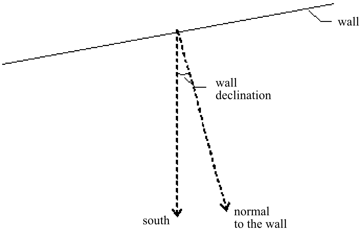
Fig. 24
— Wall declination
This parameter has to be found with a good approximation as it has a
large influence of the dial behaviour and on its design (however this
knowledge is not needed when the experimental method is used).
One of the best methods, but not the only one, is here described.
Put a plumb line in front of the wall and measure, on a horizontal table, the angle alpha between the shadow of the plumb line and the wall (Fig. 25). Take note of the date and exact time of the measurement.
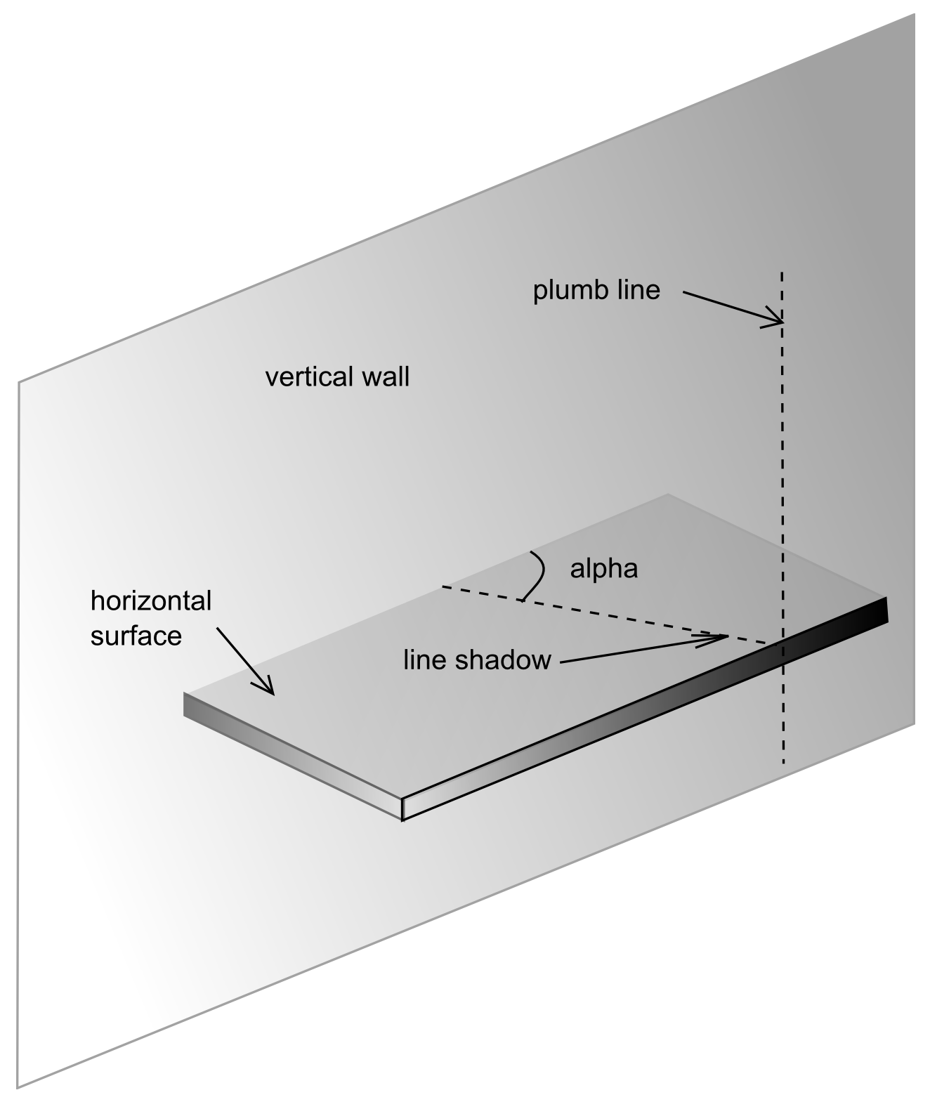
Fig. 25 — Wall declination measurement
Then compare the measured value of alpha with the solar azimuth
value at the same measurement instant (this value can be obtained for
instance by means of
Dialist’s
Companion or
Orologi Solari) and compute the wall declination as 90-alpha+azimuth.
Imagine for instance that you made three measurements on September 19th
at 10:27, 13:33 and 17:48 EST (UTC-5) in Orlando, FL (latitude
28°
32' 37" N and
longitude 81° 22' 22" W).
Let's compute the sun azimuth at these three instants.
If mathematical formulae are used, then the local sun time has to be obtained from the time zone hour as read on the wristwatch (the Central Europe Mean Time in this case) :
-
remove 1 hour because of the DST
-
remove the value of EoT (in this case EoT is negative as the sun is early with respect to the mean time)
-
remove the longitude error (the place is 6° 22' 22" that is 6.373° far from the reference meridian that is 4*6.373 = 25.491 minutes = 0:25:29 hours, this number has to be removed as the place is west to the reference meridian and sun is late)
At 10:27 we have for instance that the local time is :
10:27:00 -
1:00:00 - (-0:06:11) - 0:25:29 = 9:07:41
At this instant of time the solar azimuth has to be computed8 , in this case its value is -64.27° (with respect to the south, negative values are for times before local noon).
As an alternative it is much more simple to use a software program taking care of inserting all the required parameters (latitude, longitude, time zone, DST etc.) and so obtaining immediately the sun azimuth value.
If the alpha angle is 12.5° at 10:27, then the wall declination is :
d = 90°
– alfa + azimut
It is convenient to take several measurements at different days and/or times, to remove the most different values if any (that could contain a measurement error) and to compute the average value of the remaining measurements.
|
date |
EST time |
EoT |
true local time |
sun declination |
sun azimuth (with respect to south) |
alpha |
d |
|
19/09/2005 |
10:27:00 |
- 0:06:11 |
9:07:41 |
1.29° |
-64.27° |
12.5° |
13.23° |
|
19/09/2005 |
13:33:00 |
- 0:06:14 |
12:13:45 |
1.24° |
7.45° |
83.5° |
13.95° |
|
19/09/2005 |
17:48:00 |
- 0:06:18 |
16:25:09 |
1.18° |
79.72° |
155.2° |
14.52° |
The mean value in this case is
13.9°
or 13°
54'. As d is positive the wall is declining to west.
It is even easier to perform the same measurement at the local noon (that is 12:00 corrected with the value of EoT and with the longitude error) as at this time the sun azimuth is zero. The wall declination can so be computed simply as :
d = 90°
– alpha
As an
alternative to the execution of the above calcuilations you can use
Orologi Solari that
immediately gives the result starting from latitude, longitude, date and
time of measurement and measured angle
alpha
(see fig. 39).
Fig. 26 shows the instrument that I have manufactured for the measurement of the wall declination according to the method just described.
It consists of a square made of wood that provides a horizontal surface when applied against the wall. A spirit level is used to obtain a horizontal position. By means of a metallic support a plumb line is put in front of a sheet of paper where the shadow is casted. I mark on the paper a line parallel to the wall, the position of the shadow and the date and time of measurement. Later I measure the alpha angle by means of a protractor and the I get the wall declination from Orologi Solari.
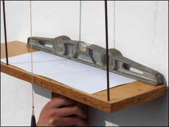
Figura 26 — Wall declination measurement
8 When computing the
sun azimuth value, the current sun declination has to be known. This can
be obtained from tables or from software programs.
Style position
Having obtained the value of all the required parameters (latitude,
longitude, wall declination) it is now possible to compute the correct
position of the style.
First of all let's define the name of every involved element
(Fig. 27 where "altezza sustilare " = "substyle height", "distanza
sustilare" = "substyle distance", "sustilare" = "substyle", "stilo
polare" = "polar style" and "meridiano locale" = "local meridian").
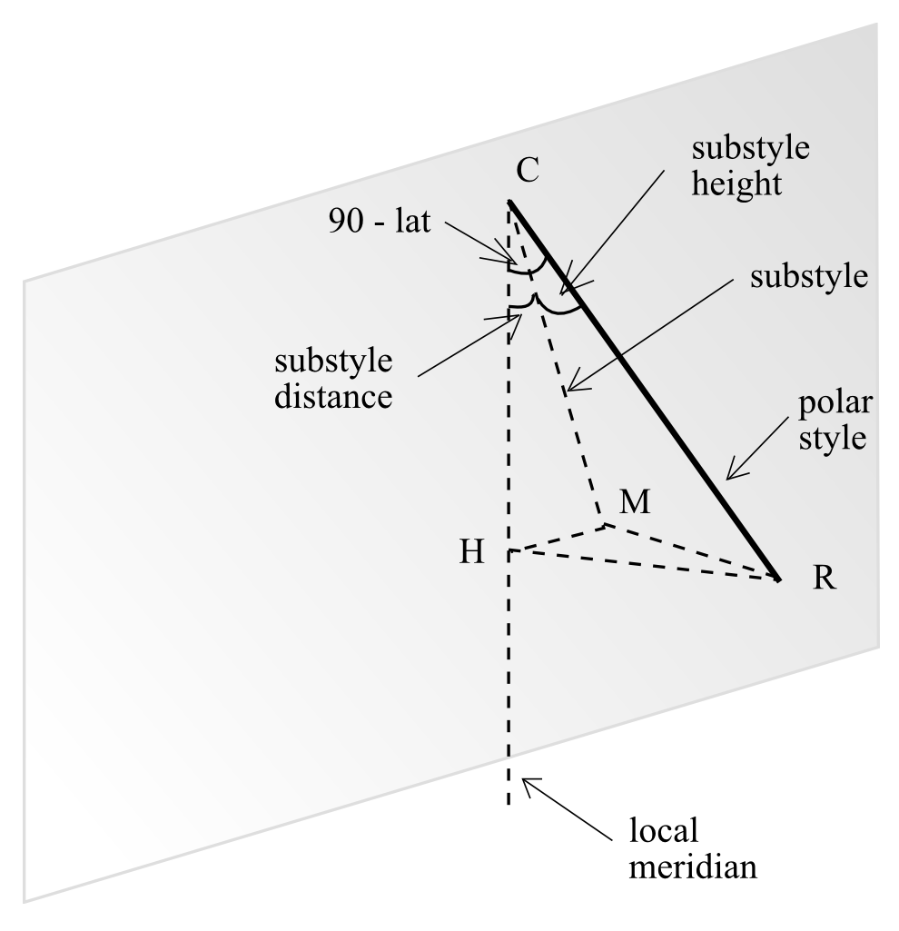
Fig. 27 — Definition of the elements of the style
We
call
substyle
the orthogonal projection CM of the style to the dial plan.
We
call
substyle distance
the angle HCM between the substyle CM and the meridian line CH.
We call substyle height the angle MCR between the style CR and the substyle CM.
We call polar style the style CR.
We call orthostyle the segment MR.
As already explained the polar style hjas to be parallel to the earth
axis.
If the wall is exactly facing south then the polar style is on a vertcal
plan orthogonal to the wall (this is the plan of the meridian) and the
angle between the style and the wall is
90°-latitude
(Fig. 28).
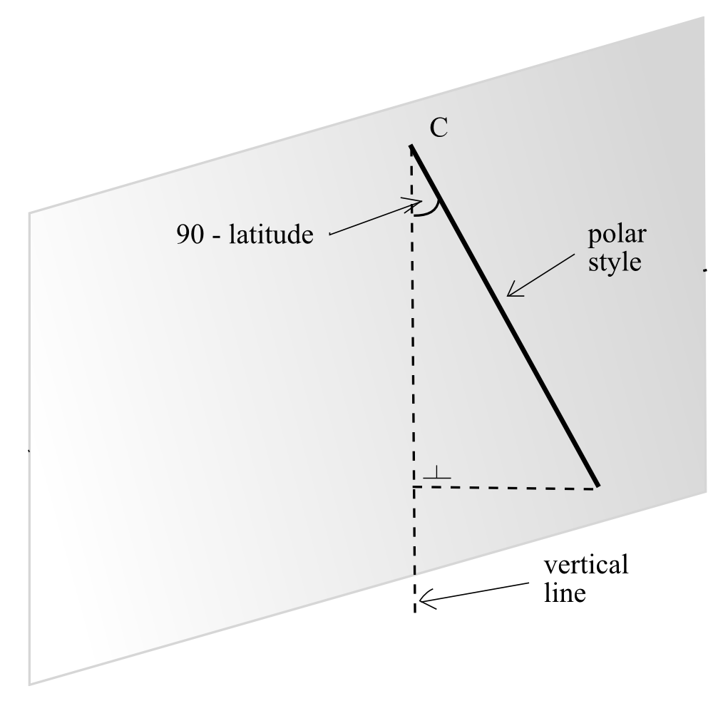
Figura 28 — Polar style on a vertical non declining wall
When the wall is declining to east or to west, imagine that the style is
fixed on the meridian plan (it has to remain parallel to the earth axis)
and the wall is rotated to east or west. We so get the two situations of
Fig. 29 and Fig. 30.
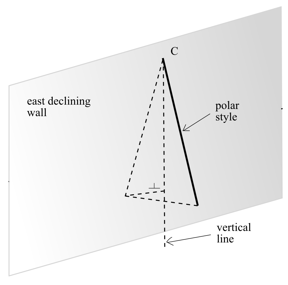
Figura
29 — Polar style on an east declining wall
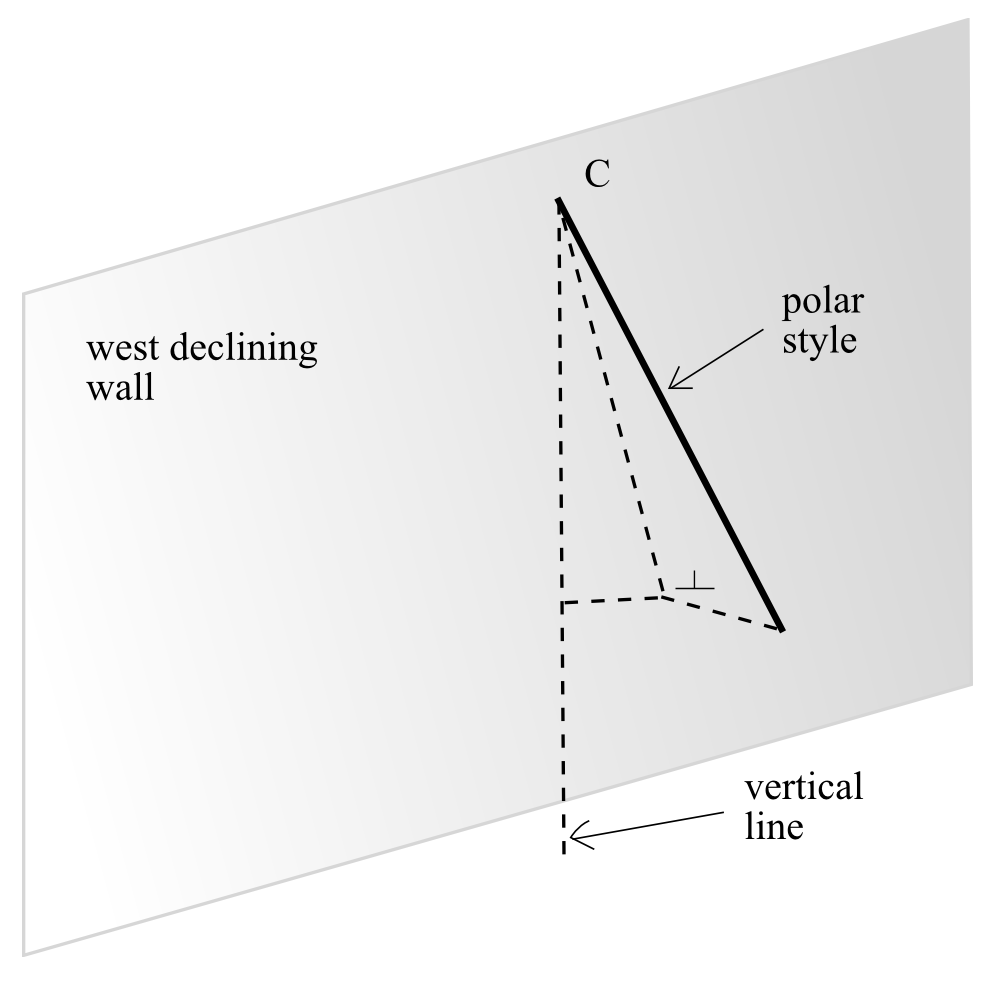
Figura
30 — Polar style on a west declining wall
The angle between the style and the wall is not anymore the one shown in fig. 28 and it has to be computed starting from the latitude and the wall declination.
As a summary :
-
in a south facing wall the substyle coincides with the local meridian line, the substyle distance is 0° and the substyle height is 90°-lat (Fig. 28)
-
in an east or west declining dial the point M (base of the orthostyle) is respectively at the left or at the right of the meridian line (Fig. 29 and Fig. 30)
In order to correctly position the style a first experimental method is available. It does not need that the wall declination is measured, it is very simple however it is not very accurate.
Manufacture the triangle CHR with cardboard or any other light and rigid
material : angle HCR is
90°-lat, angle CRH
is
lat
and angle CHR is
90°.
Put triangle side CH against a vertical line on the wall with the vertex C on the point where the polar style will be fixed.
At the local noon time (12:00 corrected with the longitude error and the
EoT) rotate the triangle around the CH side in order to obtain that the
shadow of the CR side is exactly on the vertical line (local meridian
line). This position is such that the CR side is now positioned
correctly as the polar style should be9.
A second available method for style positioning is graphical, it requires that some lines are drawn on the wall by means of ruler and compasses (see the chapter Graphical Method).
The last method, that is probably the more accurate, requires the computation of all the parameters through trigonometric formulae or simply using a software program. See chapter Mathematical Method.
Un ulteriore metodo, secondo me il più preciso, richiede di eseguire alcuni calcoli trigonometrici o, ancor più semplicemente, utilizzare programmi di calcolo già disponibili. Si veda il capitolo Metodo matematico.
9 This method, apart from the low accuracy, is only applicable to walls that are not too much declining. In fact the larger the wall declination, the more far the point C is, and as an extreme situation, when the declination is ±90º , the polar style is parallel to the wall and both point C and the meridian line are at an infinite distance.
A note on style positioning
It is not so easy to fix the style on the wall keeping the correct
required position and angles. It can be useful to have a tool similar to
that shown in fig. 31.
It is a plan tablet with suitable supports that enable to fix it to the
wall in an orthogonal position. It also includes a support for keeping
the style in the correct position while fixing it to the wall.
After having drawn the substyle line and having dug a hole for the style in the wall, the tablet is fixed to the wall taking care of the orthogonality of the tablet itself to the wall. The tablet must be put in such a way that the style will be exactly on the substyle line.
The style is then fixed to the tablet and all the style parameters (substyle height, style length, orthostyle length) are measured and checked.
When all parameters are correct the hole can be closed and the style be definitely fixed.
When the tablet is removed, it can be convenient to check the position of the vertical line CH and if necessary to draw it again.
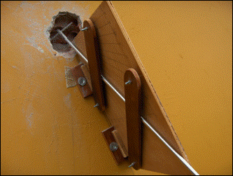
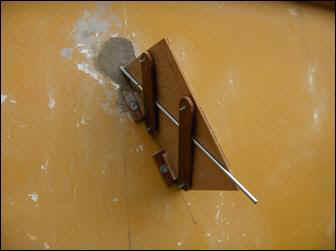
Fig. 31
— How to position and to fix the style on the wall
Auxiliary equatorial disc method
Although this method is not actually easy to implement, it has the advantage of giving a better understanding of how a sundial works. In fact sun rays are here simuklated in their path from the style tip to the shadow on the wall.
Fig. 17 showed how an equatorial dial can explain how a dial on a vertical wall works.
By means of that concept, when the polar style has already been positioned on the wall, it is possible to draw the hour lines and if needed the day lines too without any computation nor any complex graphical processes.
However the tool shown in fig. 32 has to be manufactured.
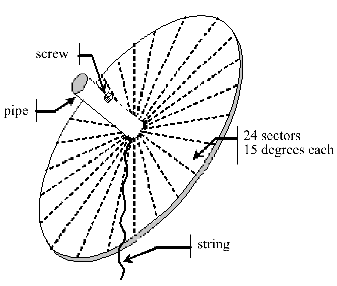
Fig. 32 — Auxiliary equatorial disc
This is again a disc that has been divided in 24 sectors 15 degrees
each. At the center of a disc there is now a pipe, orthogonal to the
disc, that is large enough to include the style on the wall A screw on
the pipe allows to fix the pipe on the style in the desired position. A
string is connected to the pipe and it will simulate the sun rays and
will permit to draw the hour lines on the wall.
Having correctly fixed the style to the wall, the disc with the pipe is
put on the style and then it is fixed by means of the screw by means of
one of the two following methods :
1. Sundial
showing local time (with no longitude correction
- Fig. 33)
Tighten the string so that it is parallel to the disc surface and it
touches the vertical line drawn from the point C (this is the meridian
line and it shows the local noon) then rotate the disc so that one of
the lines drawn on the disc coincides with the string and fix the disc
in this position with the screw. Yhis line on the disc is the 12:00
line, at the left and the right there are the preceding and the
following hours.
As an alternative (although less accurate) it is possible to position the
disc with a spirit level so that the lines of 6:00 and 18:00 are
horizontal.
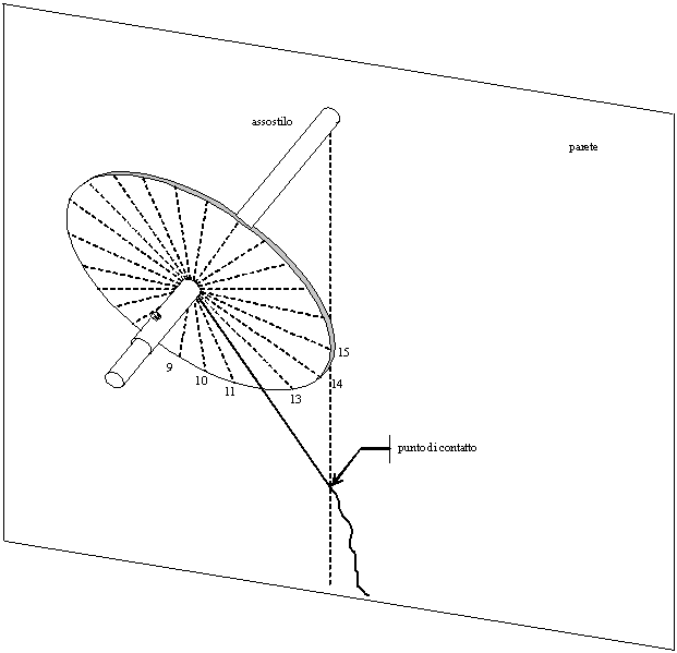
Fig. 33
— How to position the auxiliary equatorial disc (without longitude
correction)
("assostilo" = "polar style" , "punto di contatto" = "point of contact" ,
"parete" = "wall")
2. Sundial showing the
time zone time (with longitude correction
- Fig. 34)
First of all in a sector of the disc we have to draw a line
corresponding to the local longitude : compute the difference between
the local and the reference meridian longitude, then mark the computed
angle on the disc as shown in fig. 34.
Then procede as in case 1 but now the string will have to coincide with
the line just drawn and on the wall it will still touch the vertical
line from C (that is still the local noon but it is not the time zone
noon, this will be on the following 15 degrees line).
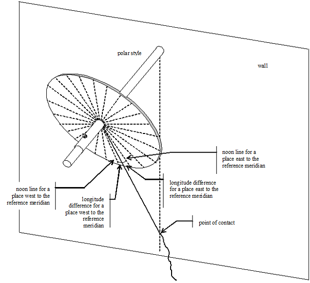
Fig. 34
— How to position the auxiliary equatorial disc (with longitude
correction)
When drawing on the disc the line corresponding to the difference in longitude, in order to know if it has to be put to the left or to the right of the 15 degrees line, it is worthy to note that :
-
for a place to the west of the reference meridian, the noon line is drawn on the wall at the left of the vertical line (local noon)
-
for a place to the east of the reference meridian, the noon line is drawn on the wall at the right of the vertical line (local noon)
In both cases the following hour lines are found moving
the string from sector to sector on the disc, keeping always the string
parallel to the disc and coincident with the 15 degrees lines and
marking the point where the string touches the wall.
All these points, when connected to the center C, would give the hour lines.
In case 1. the 12:00 line will be coincident with the vertical line from C (meridian line).
In case 2. noon will be at the left of the vertical line for places west to the reference meridian and at the right for places east to the reference meridian.
In fig. 35 the situation is shown for a place at the west of the time zone meridian.
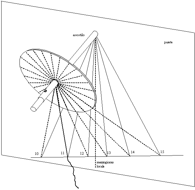
Fig. 35 — Hour line tracing with the auxiliary equatorial disc
The method here described corresponds to the simulation, by means of the string, of the sun rays path in the equinox day (rays parallel to the earth equator) and then finding the points where the rays hit the wall. The string should be left free to rotate around the central pipe while still keeping the same lock point on the style so that, when tightened, it goes through a linear path from the center of the pipe to the point on the wall.
It is worthy to note that the marked points are the ones that are
touched at the equinox day by the shadow
If the solstice lines have to be traced, a new tool is needed. It should be manufactured in order to have again a string that simulates the sun rays that are inclined ± 23˚ 26' with respect to the eart equator (and of the auxiliary disc).
It can be made again of a pipe to be fixed on the style, a string fixed to the pipe and a graduated scale that allows to incline the string to the desired value (Fig. 36).
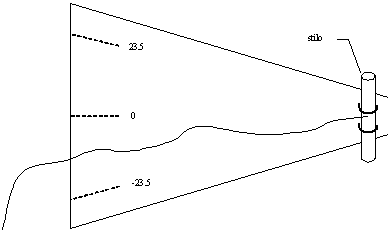
Fig. 36
— Instrument to trace day lines
For each hour line that has been traced, the tool has to be fixed in a position such that the string, when tightened and kept parallel to the instrument plate, will touch the hour line. Then the string is inclined of the three angular values and the three intersections of the hour line with the solstices and the equinox lines are found. Again the point where the string is fixed to the style is the point where the style nodus has to be put.
This method can be used on whichever plan surface, even if not vertical, provided that the style is properly positioned. It is so possible in a simple way to design a sundial on whichever planar surface. Moreover this same method could even be used, with some care, to draw sundials on non planar surfaces.
Graphical method
The drawback of this method is the time needed for the drawing and the resulting low accuracy due to the sum of small errors that can be done during the process.
However the resulting drawing is so fascinating that it would be worthy to leave on the wall all the construction lines.
The first step is to define the position of the style. For a south facing wall we have seen that the style is on a plan orthogonal to the wall and it has a 90° - latitude angle with respect to the wall. For a declining wall the substyle distance and height have to be found.
The process is essentially to overturn to the wall plan the two triangles CHR and HMR in fig. 27.
First of all trace a horizontal line AB below the point C that is the center of the hour lines and the point where the style is fixed to the wall (Fig. 37).
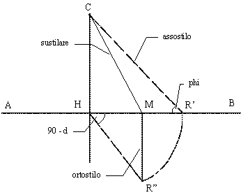
Fig. 37
— Graphical determination of substyle distance and height
("sustilare" = "substyle" , "assostilo" = "polar style" , "ortostilo" =
"orthostyle")
Now trace the line CR' such that the angle HR'C is equal to the latitude φ. Segment CR' is equal to the length of the style. R' is at the right of C for a west declination, at the left of C for an east declination.
From H trace the line HR" such that the angle
R”HR’ is equal to the complement of the wall declinatio, i.e. 90°- d.
From
H draw an arc with ray HR’ that will cross HR” in R”. From R” draw the
line perpendicular to AB finding so the point M.
The straight line CM is the required substyle line and R"M is the length of the orthostyle.
The gnomonic triangle is made of
CR’ (polar style), CM (substyle) and RM (orthostyle).
We have now to draw the hour lines.
The procedure is very similar to what we have done with the auxiliary equatorial disc, this disc is projected to the wall surface and again all the hour lines are obtained from the disc divided into 24 sectors.
This procedure can be found looking at the references in the appendix, for instance in René Rohr book.
First of all let's overturn to the plan the CMR triangle of fig. 27 : from point M of the substyle line CM found in fig. 37 draw the perpendicular MR'" (Fig. 38) and with centre in the same point M draw an arc with ray MR" until reaching the line MR'" in R'". The triangle CMR'" is the triangle CMR of fig. 27.
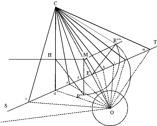
Fig. 38
— Graphical drawing of hour lines
From R'" draw the perpendicular to CR'" to the point E of the substyle CM; from E draw the perpendicular ST to the substyle CM. This is the equinox line and corresponds to the straight line in fig. 35.
We now have to overturn the equatorial disc to the wall plan: with centre in E draw an arc with ray ER'" to meet the substyle in O. With center in O draw a circle with arbitrary ray length. Find on the intersection d between the vertical line CH and the equinox line ST, then trace the line dO. Divide the circle in 15 degrees sectors starting from the line dO.
Extend the rays just found to the line ST and mark the intersection point c, e, f etc. and from these points trace the hour lines Cc, Cd ... Cm. The line Cd correspond to the local 12:00.
If the circle is divided in 7.5 degrees sectors, half hour lines can be found.
If the dial has to show the reference meridian time instead of the local time, then the line Od should correspond not to 0 degrees but to the error in degrees between the sundial place and the reference meridian (exactely as in fig. 34). In this way all the rays of the circle will rotate of this angular value and all the points c, d etc. will move to a different position. The vertical line Cd will still correspond to the local noon but not anymore to the reference time zone noon.
Mathematical method
This is the most accurate method that can be used for the design of a sundial, although it is the less intuitive and it gives no help in understanding how a sundial works.
By means of trigonometri formulae (see René Rohr book or “The British Sundial Society Glossary”) and starting from the values of latitude, longitude and wall declination, the position of hour lines and day lines can be computed.
Of course these computations were long and difficult years ago but they are now easy to do with a personal computer and a spread sheet program.
Moreover, if you do not want to perform all the computation by yourself, there are several freeware programs can perform every computation and then give you a graphical presentation of the resulting dial.
On my web site at the address http://digilander.libero.it/orologi.solari/download_enu my freeware program Orologi Solari is available for download. It allows the design of :
-
horizontal, vertical, inclined etc dials
-
analemmatic, azimuth, monofilar dials
-
french, italic, babilonic, temporal, ecliptic, ascendant etc. hour lines
-
analemma
-
day lines
Moreover it includes some useful and not so common tools :
-
wall declination computation
-
wall lighting conditions computation
-
simulation of the sundial
-
reverse engineering of ancient dials
An on line contextual help is available for instructions on using the program.
Together with the program a screen saver is available for the simulation of your own sundial.
If you need more details on Orologi Solari please see the help file OrologiSolariHelp.
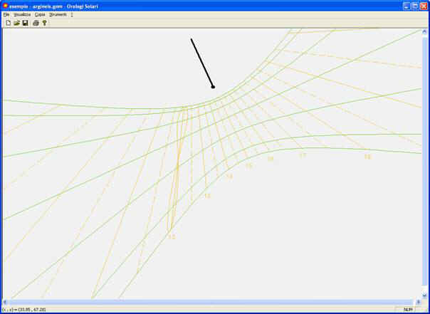
Fig. 39 - Orologi Solari program
updated on venerdì 06 marzo 2015